
Product details
Product Introduction
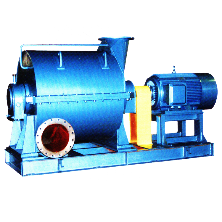
On the basis of absorbing new technology inside and outside China, Changsha Blower Co.,Ltd. and Xian Jiaotong University teamed up to develop the centrifugal blowers, that include multistage low speed centrifugal blowers, single-stage low speed centrifugal blowers and single-stage high speed centrifugal blowers, three series, more than 100 models, with the capacity 50~2000m3/min and pressure rise 10~150kPa.
● C Series Multistage Low Speed Centrifugal Blower
With capacity 50~1000m3/min, pressure rise 19.6~150kPa, and construction of single intaking, double supporting, multistage, the C series multistage low speed centrifugal blowers are widely used in water treatment aeration, power plant desulfurization and oxidation, melting furnace, coal washery, mine flotation, chemical gas making, vacuum, etc. They also can be used to convey special gases such as coal gas and biogas by changing construction suitably.
Derived Models
The following models are derived from the above three models:
●Sewage treatment blower capacity: 50~600m3/min pressure rise:49.0~98kPa
●Desulfurization&oxidation blower capacity: 60~800m3/minpressure rise: 49.0~150kPa
●Sulfur dioxide blower capacity: 200~2000m3/minpressure rise: 26.4~53.9kPa
●Gas-making furnace blower capacity: 300~1500m3/minpressure rise: 23.5~34.3kPa
●Cupola blower capacity:50~350m3/minpressure rise: 9.8~29.4kPa
●Smelting furnace blower capacity:100~1000m3/minpressure rise: 49.0~150kPa
●Coal gas blowercapacity:100~1250m3/minpressure rise: 19.6~53.9kPa
●Coal flotation&washing blowercapacity:50~500m3/minpressure rise:19.6~68.6kPa
Model Selection
Model Introduction
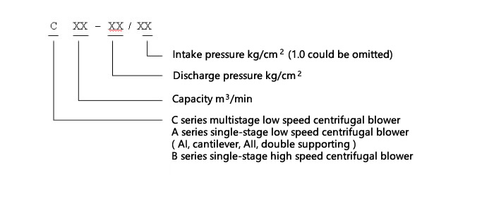
For example:
C300–1.7/1.0
It means a multistage centrifugal blower, when temperature is 20℃, intake pressure is 1.0kgf/cm2(98kPa), relative humidity is 50%, the capacity is 300 m3/min, and discharge pressure is 1.7kgf/cm2(pressure rise 68.6kPa).
Model Selection Drawing

The performance range of blower could be determined approximately by capacity and pressure as drawing show, plus another conditions, a precise model could be confirmed by professionals.
Elements of Model Selection
● Technical conditions
Medium, intake conditions, capacity, pressure rise (or discharge pressure), ambient conditions.
●Model Selection Calculation
If the medium is air, intake conditions and ambient conditions are as same as the catalogue conditions, the model could be selected directly according to capacity and pressure rise (or discharge pressure) among the catalogue models.
If the medium, or intake conditions, or ambient conditions, are not as same as the catalogue conditions, (for example, the temperature or density is very different.) then the parameters of model selection should be calculated and rectified.
(1) Ambient temperature
The design temperature of blower is 20℃. For aeration blower, every 1℃ that intake temperature increases will lead a 0.002kgf/cm2 decline of discharge pressure. Thus, when the temperature is 40℃ in summer, the discharge pressure will decline 0.04kgf/cm2
(1) Altitude
The design intake pressure of blower is 1.0kgf/cm2. When the altitude is high, the capacity and discharge pressure should be rectified according to local atmosphere pressure.
(2) Capacity Conversion
If the standard capacity at standard condition(0℃,1.033kgf/cm2) is QN, then the actual intake capacity at intake condition (ts,Ps) is Qs, there is a conversion formula:
Qs=( ts+273)/273×1.033/ Ps×QN
ts: intake temperature,℃
Ps: intake pressure,kgf/cm2
(3) Conversion between pressure unit in common use
9.8kPa=0.1 kgf/cm2=1000mmH2O=98mbar=0.0967atm=73.5mmHg
● Features:
◎ Due to the advanced design of aerodynamic, the impeller is of high efficiency.
◎ The casing is of horizontal division welding structure, simple and light in weight.
◎ Due to flat performance curve, performance can be easily adjusted.
◎ Reasonable and advanced construction, reduces the wearing parts, and makes the operation and maintenance convenient.
● Typical Performance Data of Multistage Centrifugal Blower
deliver medium | Intake condition | pressure rise (kpa) | La(kW) | Po(kW) | |||
capacity (m3/min) | temperature (℃) | ||||||
C50-1.2 | air | 50 | 1.0 | 20 | 19.6 | 21 | 30 |
C50-1.3 | air | 50 | 1.0 | 20 | 29.4 | 33.5 | 45 |
C50-1.4 | air | 50 | 1.0 | 20 | 39.2 | 43.7 | 55 |
C50-1.5 | air | 50 | 1.0 | 20 | 49.0 | 53.2 | 75 |
C50-1.6 | air | 50 | 1.0 | 20 | 58.8 | 67.9 | 90 |
C60-1.2 | air | 60 | 1.0 | 20 | 19.6 | 27.1 | 37 |
C60-1.3 | air | 60 | 1.0 | 20 | 29.4 | 40.4 | 55 |
C60-1.4 | air | 60 | 1.0 | 20 | 39.2 | 50.7 | 75 |
C60-1.5 | air | 60 | 1.0 | 20 | 49.0 | 69.1 | 90 |
C60-1.6 | air | 60 | 1.0 | 20 | 58.8 | 79.1 | 110 |
C80-1.2 | air | 80 | 1.0 | 20 | 19.6 | 35.2 | 45 |
C80-1.3 | air | 80 | 1.0 | 20 | 29.4 | 53.3 | 75 |
C80-1.4 | air | 80 | 1.0 | 20 | 39.2 | 70.7 | 90 |
C80-1.5 | air | 80 | 1.0 | 20 | 49.0 | 89.5 | 110 |
C80-1.6 | air | 80 | 1.0 | 20 | 58.8 | 104 | 132 |
C80-1.7 | air | 80 | 1.0 | 20 | 68.6 | 120 | 160 |
C100-1.2 | air | 100 | 1.0 | 20 | 19.6 | 45.7 | 55 |
C100-1.3 | air | 100 | 1.0 | 20 | 29.4 | 68.0 | 90 |
C100-1.4 | air | 100 | 1.0 | 20 | 39.2 | 90.0 | 110 |
C100-1.5 | air | 100 | 1.0 | 20 | 49.0 | 111 | 132 |
C100-1.6 | air | 100 | 1.0 | 20 | 58.8 | 131 | 160 |
C100-1.7 | air | 100 | 1.0 | 20 | 68.6 | 153 | 185 |
C125-1.2 | air | 125 | 1.0 | 20 | 19.6 | 57 | 75 |
C125-1.3 | air | 125 | 1.0 | 20 | 29.4 | 85.0 | 110 |
C125-1.4 | air | 125 | 1.0 | 20 | 39.2 | 111 | 132 |
C125-1.5 | air | 125 | 1.0 | 20 | 49.0 | 137 | 160 |
C125-1.6 | air | 125 | 1.0 | 20 | 58.8 | 163 | 185 |
C125-1.7 | air | 125 | 1.0 | 20 | 68.6 | 188 | 220 |
C150-1.2 | air | 150 | 1.0 | 20 | 19.6 | 66.2 | 90 |
C150-1.3 | air | 150 | 1.0 | 20 | 29.4 | 97.7 | 132 |
C150-1.4 | air | 150 | 1.0 | 20 | 39.2 | 129 | 160 |
C150-1.5 | air | 150 | 1.0 | 20 | 49.0 | 160 | 185 |
C150-1.6 | air | 150 | 1.0 | 20 | 58.8 | 191 | 220 |
C150-1.7 | air | 150 | 1.0 | 20 | 68.6 | 221.3 | 250 |
C150-1.8 | air | 150 | 1.0 | 20 | 78.4 | 249.1 | 315 |
C200-1.2 | air | 200 | 1.0 | 20 | 19.6 | 87.6 | 110 |
C200-1.3 | air | 200 | 1.0 | 20 | 29.4 | 129.3 | 160 |
C200-1.4 | air | 200 | 1.0 | 20 | 39.2 | 171 | 200 |
C200-1.5 | air | 200 | 1.0 | 20 | 49.0 | 212 | 250 |
C200-1.6 | air | 200 | 1.0 | 20 | 58.8 | 241 | 280 |
C200-1.7 | air | 200 | 1.0 | 20 | 68.6 | 279 | 355 |
C200-1.8 | air | 200 | 1.0 | 20 | 78.4 | 327 | 400 |
C250-1.2 | air | 250 | 1.0 | 20 | 19.6 | 109 | 132 |
C250-1.3 | air | 250 | 1.0 | 20 | 29.4 | 161 | 185 |
C250-1.4 | air | 250 | 1.0 | 20 | 39.2 | 212 | 250 |
C250-1.5 | air | 250 | 1.0 | 20 | 49.0 | 263 | 315 |
C250-1.6 | air | 250 | 1.0 | 20 | 58.8 | 312 | 355 |
C250-1.7 | air | 250 | 1.0 | 20 | 68.6 | 360 | 450 |
C250-1.8 | air | 250 | 1.0 | 20 | 78.4 | 406 | 500 |
C300-1.3 | air | 300 | 1.0 | 20 | 29.4 | 191 | 220 |
C300-1.4 | air | 300 | 1.0 | 20 | 39.2 | 251 | 315 |
C300-1.5 | air | 300 | 1.0 | 20 | 49.0 | 311 | 400 |
C300-1.6 | air | 300 | 1.0 | 20 | 58.8 | 369 | 450 |
C300-1.7 | air | 300 | 1.0 | 20 | 68.6 | 426 | 500 |
C300-1.8 | air | 300 | 1.0 | 20 | 78.4 | 480 | 560 |
C300-1.9 | air | 300 | 1.0 | 20 | 88.2 | 532 | 630 |
C350-1.3 | air | 350 | 1.0 | 20 | 29.4 | 150 | 185 |
C350-1.4 | air | 350 | 1.0 | 20 | 39.2 | 221 | 250 |
C350-1.5 | air | 350 | 1.0 | 20 | 49.0 | 291 | 355 |
C350-1.6 | air | 350 | 1.0 | 20 | 58.8 | 361 | 450 |
C350-1.7 | air | 350 | 1.0 | 20 | 68.6 | 428 | 500 |
C350-1.8 | air | 350 | 1.0 | 20 | 78.4 | 552 | 630 |
C350-1.9 | air | 350 | 1.0 | 20 | 88.2 | 611 | 710 |
C400-1.3 | air | 400 | 1.0 | 20 | 29.4 | 249 | 315 |
C400-1.4 | air | 400 | 1.0 | 20 | 39.2 | 328 | 400 |
C400-1.5 | air | 400 | 1.0 | 20 | 49.0 | 404 | 500 |
C400-1.6 | air | 400 | 1.0 | 20 | 58.8 | 482 | 560 |
C400-1.7 | air | 400 | 1.0 | 20 | 68.6 | 557 | 630 |
C400-1.8 | air | 400 | 1.0 | 20 | 78.4 | 626 | 710 |
C400-1.9 | air | 400 | 1.0 | 20 | 88.2 | 694 | 800 |
C400-2 | air | 400 | 1.0 | 20 | 98 | 775 | 900 |
C500-1.5 | air | 500 | 1.0 | 20 | 49.0 | 505 | 630 |
C500-1.6 | air | 500 | 1.0 | 20 | 58.8 | 603 | 710 |
C500-1.7 | air | 500 | 1.0 | 20 | 68.6 | 701 | 800 |
C500-1.8 | air | 500 | 1.0 | 20 | 78.4 | 789 | 900 |
C500-1.9 | air | 500 | 1.0 | 20 | 88.2 | 874 | 1000 |
C500-2.0 | air | 500 | 1.0 | 20 | 98 | 969 | 1120 |
C500-2.1 | air | 500 | 1.0 | 20 | 107.8 | 1066 | 1250 |
C600-1.5 | air | 600 | 1.0 | 20 | 49.0 | 606 | 710 |
C600-1.6 | air | 600 | 1.0 | 20 | 58.8 | 723 | 900 |
C600-1.7 | air | 600 | 1.0 | 20 | 68.6 | 841 | 1000 |
C600-1.8 | air | 600 | 1.0 | 20 | 78.4 | 946 | 1120 |
C600-1.9 | air | 600 | 1.0 | 20 | 88.2 | 1048 | 1250 |
C600-2.0 | air | 600 | 1.0 | 20 | 98 | 1162 | 1400 |
C600-2.1 | air | 600 | 1.0 | 20 | 107.8 | 1269 | 1400 |
C600-2.2 | air | 600 | 1.0 | 20 | 117.6 | 1374 | 1600 |
C600-2.5 | air | 600 | 1.0 | 20 | 147 | 1635 | 1800 |
C800-1.5 | air | 800 | 1.0 | 20 | 49 | 805 | 900 |
C800-2.0 | air | 800 | 1.0 | 20 | 98 | 1549 | 1800 |
C800-2.5 | air | 800 | 1.0 | 20 | 147 | 2190 | 2500 |
C1000-1.5 | air | 1000 | 1.0 | 20 | 49 | 1060 | 1250 |
C1000-2.0 | air | 1000 | 1.0 | 20 | 98 | 1936 | 2240 |
C1000-2.5 | air | 1000 | 1.0 | 20 | 147 | 2738 | 2500 |
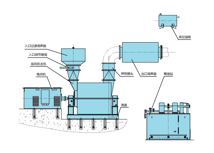
● Layout of Multistage Centrifugal Blower
Layout of Multistage Centrifugal Blower (rolling bearing)
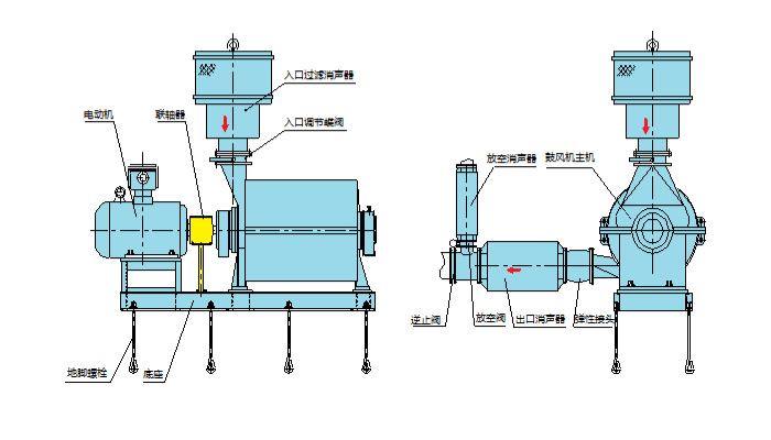
Layout of Multistage Centrifugal Blower(sliding bearing)
● Dimensions of Multistage Centrifugal Blower
Installation Dimensions of C Series Multistage Low Speed Centrifugal Blower(rolling bearing)
(This is only for reference, the foundation should be built on the basis of contract drawing.)
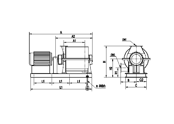
Type | A | A1 | A2 | B | C | H2 | H1 | H | L | L1 | DN1 | DN2 | n-Mdxh |
C60-1.4 | 2670 | 950 | 1590 | 700 | 880 | 885 | 460 | 1635 | 2300 | 650 | 250 | 250 | 8-M24x500 |
C60-1.5 | 2780 | 1050 | 1680 | 700 | 880 | 885 | 460 | 1635 | 2400 | 700 | 250 | 250 | 8-M24x500 |
C80-1.5 | 2980 | 1050 | 1600 | 700 | 880 | 885 | 460 | 1635 | 2600 | 750 | 300 | 250 | 8-M24x500 |
C80-1.7 | 3110 | 1415 | 1800 | 700 | 880 | 885 | 460 | 1635 | 3000 | 900 | 300 | 250 | 8-M24x500 |
C100-1.2 | 2440 | 710 | 1510 | 800 | 1150 | 980 | 400 | 1635 | 2000 | 600 | 350 | 300 | 8-M24x500 |
C100-1.3 | 2740 | 890 | 1690 | 800 | 1150 | 980 | 400 | 1635 | 2300 | 650 | 350 | 300 | 8-M24x500 |
C100-1.4 | 3110 | 1070 | 1870 | 800 | 1150 | 980 | 400 | 1635 | 2400 | 700 | 350 | 300 | 8-M24x500 |
C100-1.5 | 3180 | 1070 | 1870 | 800 | 1150 | 980 | 400 | 1635 | 2500 | 700 | 350 | 300 | 8-M24x500 |
C100-1.6 | 3360 | 1250 | 2050 | 800 | 1150 | 980 | 400 | 1635 | 3000 | 900 | 350 | 300 | 8-M24x630 |
C100-1.7 | 3540 | 1430 | 2230 | 800 | 1150 | 980 | 400 | 1635 | 3000 | 900 | 350 | 300 | 8-M24x630 |
C125-1.2 | 2510 | 710 | 1510 | 800 | 1150 | 980 | 400 | 1635 | 2100 | 600 | 350 | 300 | 8-M24x500 |
C125-1.3 | 2930 | 890 | 1690 | 800 | 1150 | 980 | 400 | 1635 | 2500 | 700 | 350 | 300 | 8-M24x500 |
C125-1.4 | 3180 | 1070 | 1870 | 800 | 1150 | 980 | 400 | 1635 | 2800 | 800 | 350 | 300 | 8-M24x500 |
C125-1.5 | 3180 | 1070 | 1870 | 800 | 1150 | 980 | 400 | 1635 | 2800 | 800 | 350 | 300 | 8-M24x500 |
C125-1.6 | 3360 | 1250 | 2050 | 800 | 1150 | 980 | 400 | 1635 | 3000 | 900 | 350 | 300 | 8-M24x630 |
C125-1.7 | 3770 | 1430 | 2230 | 800 | 1150 | 980 | 400 | 1635 | 3150 | 900 | 350 | 300 | 8-M24x630 |
C150-1.2 | 2450 | 600 | 1400 | 800 | 1150 | 980 | 495 | 1830 | 2300 | 650 | 400 | 350 | 8-M24x630 |
C150-1.3 | 2910 | 800 | 1600 | 800 | 1150 | 980 | 495 | 1830 | 2500 | 700 | 400 | 350 | 8-M24x630 |
C150-1.4 | 3110 | 1000 | 1800 | 800 | 1150 | 980 | 495 | 1830 | 2750 | 800 | 400 | 350 | 8-M30x800 |
C150-1.5 | 3310 | 1200 | 2000 | 800 | 1150 | 980 | 495 | 1830 | 2950 | 900 | 400 | 350 | 8-M30x800 |
C150-1.6 | 3540 | 1200 | 2000 | 800 | 1150 | 980 | 495 | 1830 | 2950 | 900 | 400 | 350 | 8-M30x800 |
C150-1.7 | 3760 | 1400 | 2200 | 800 | 1150 | 980 | 495 | 1830 | 3150 | 900 | 400 | 350 | 8-M30x800 |
C150-1.8 | 3940 | 1600 | 2400 | 800 | 1150 | 980 | 495 | 1830 | 3350 | 1000 | 400 | 350 | 8-M30x800 |
C200-1.2 | 2740 | 660 | 1500 | 800 | 1200 | 980 | 495 | 1830 | 2400 | 700 | 400 | 400 | 8-M24x630 |
C200-1.3 | 3010 | 860 | 1700 | 800 | 1200 | 980 | 495 | 1830 | 2700 | 800 | 400 | 400 | 8-M24x630 |
C200-1.4 | 3210 | 1060 | 1900 | 800 | 1200 | 980 | 495 | 1830 | 2900 | 850 | 400 | 400 | 8-M24x630 |
C200-1.5 | 3640 | 1250 | 2100 | 800 | 1200 | 980 | 495 | 1830 | 3200 | 900 | 400 | 400 | 8-M30x800 |
C200-1.6 | 3840 | 1450 | 2300 | 800 | 1200 | 980 | 495 | 1830 | 3400 | 950 | 400 | 400 | 8-M30x800 |
C200-1.7 | 4450 | 1450 | 2300 | 800 | 1200 | 980 | 495 | 1830 | 3800 | 850 | 400 | 400 | 10-M30x800 |
C200-1.8 | 4660 | 1660 | 2510 | 800 | 1200 | 980 | 495 | 1830 | 4000 | 900 | 400 | 400 | 10-M30x800 |
C250-1.2 | 2740 | 600 | 1430 | 800 | 1250 | 1050 | 620 | 1900 | 3400 | 950 | 500 | 450 | 8-M30x800 |
C250-1.3 | 2945 | 790 | 1635 | 800 | 1250 | 1050 | 620 | 1900 | 3450 | 950 | 500 | 450 | 8-M30x800 |
C250-1.4 | 3075 | 790 | 1635 | 800 | 1250 | 1050 | 620 | 1900 | 3650 | 850 | 500 | 450 | 10-M30x800 |
C250-1.5 | 3275 | 990 | 1835 | 800 | 1250 | 1050 | 620 | 1900 | 3900 | 850 | 500 | 450 | 10-M30x800 |
C250-1.6 | 4175 | 1140 | 2025 | 800 | 1250 | 1050 | 620 | 1900 | 4050 | 900 | 500 | 450 | 10-M30x800 |
C250-1.7 | 4215 | 1180 | 2065 | 800 | 1250 | 1050 | 620 | 1900 | 4050 | 900 | 500 | 450 | 10-M30x800 |
C250-1.8 | 4385 | 1350 | 2235 | 800 | 1250 | 1050 | 620 | 1900 | 4250 | 950 | 500 | 450 | 10-M30x800 |
C300-1.5 | 4155 | 990 | 1835 | 800 | 1250 | 1050 | 620 | 1900 | 3950 | 900 | 500 | 450 | 10-M30x800 |
C300-1.7 | 4385 | 1180 | 2065 | 800 | 1250 | 1050 | 620 | 1900 | 4050 | 900 | 500 | 450 | 10-M30x800 |
● The supply scope of multistage centrifugal blower
No. | Standard | Optional | ||
Name | Qty | Name | Qty | |
1 | blower | 1 | Inlet silencer | 1 |
2 | Lubricating device | 1 | Discharge silencer | 1 |
3 | Motor | 1 | Outlet flexible joint | 1 |
4 | Inlet control valve | 1 | Outlet electric butterfly valve | 1 |
5 | Coupling | 1 | Atmospheric silencer | 1 |
6 | Coupling protector | 1 | Atmospheric electric butterfly valve | 1 |
7 | base | 1 | Check valve | 1 |
8 | Anchor bolt,nut,washer | 1 | Primary instrument | 1 |
9 | Spare parts | 1 | Spot control cabinet | 1 |
*For the blower with rolling bearing, the lubricating device is included in the blower, for the blower with sliding bearing, the thin oil station is equipped.